Pitch Estimation In Autonomous Driving
Pitch Estimation
The vehicle’s pose, the offline or online calibrated extrinsic parameters, and the pitch angle required for real-time IPM (the angle between the camera’s optical axis and the ground) — these three concepts are, to some extent, easily confused and interrelated, as shown in the figure below: 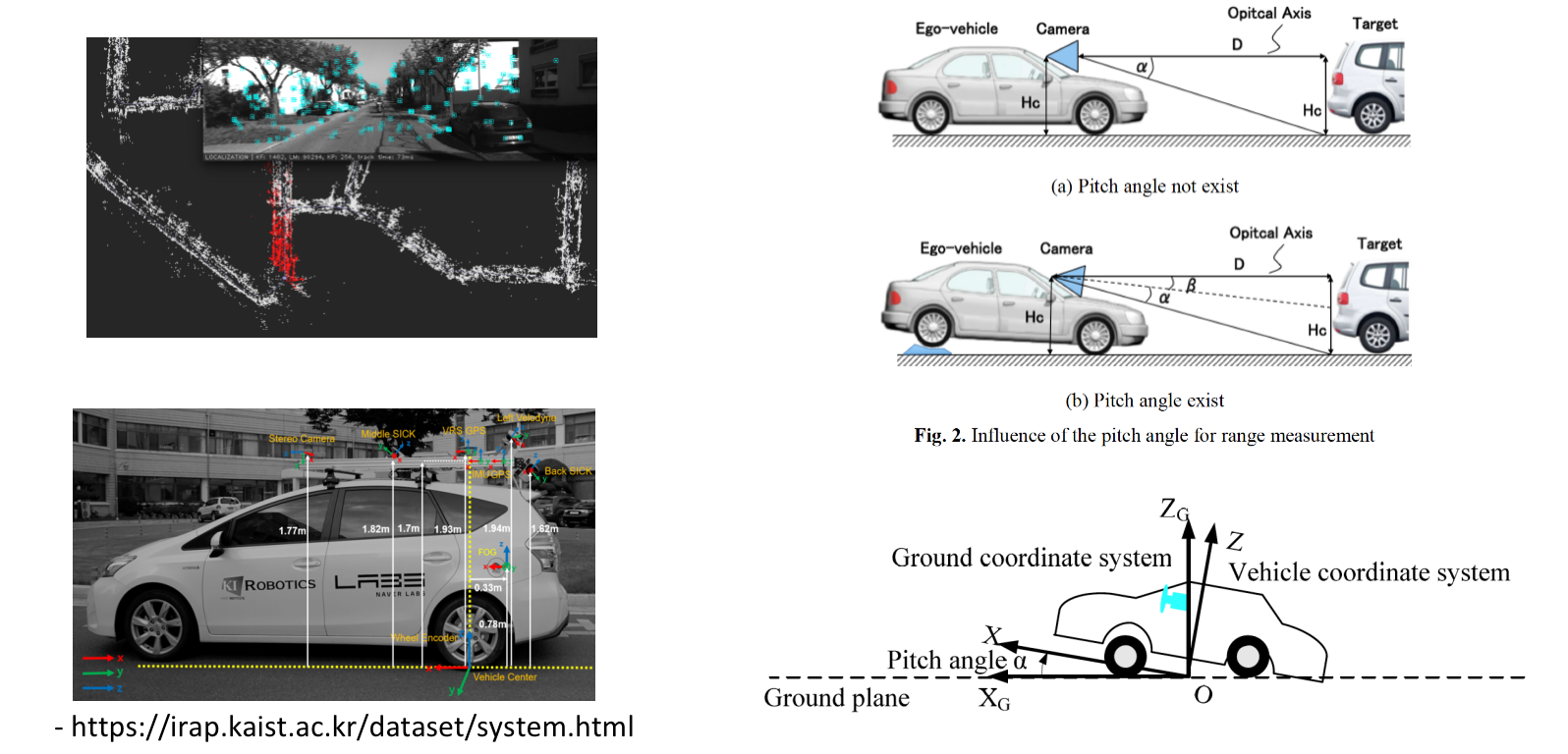
Taking map-based localization as an example, the pose refers to estimating the transform of the vehicle relative to the world at every moment, where the world here refers to the map coordinate frame. The calibrated extrinsics refer to the transform of the sensor coordinate frame relative to the vehicle coordinate frame. The pitch angle estimated in real time refers to the angle between the camera’s optical axis and the horizontal ground. Because of the undulation of the ground or the acceleration and deceleration of the vehicle, this angle changes; we want to estimate this transform in real time, i.e., the transform between the camera coordinate frame and the ground coordinate frame, or equivalently the transform between the vehicle coordinate frame and the ground coordinate frame.
A common way to eliminate the effect of the image’s perspective projection is to use IPM (Inverse Perspective Mapping). The premise of IPM is that we need to know the transform of the camera relative to the ground, whereas through calibration we can only obtain the transform between the camera and the vehicle. Under normal conditions, we use fixed extrinsics to warp between the front-view image and the BEV image. However, due to uneven ground, vehicle acceleration and deceleration, and going up and down slopes, the camera’s angle (relative to the ground) varies around the extrinsics as its mean; we need to estimate this variation in real time in order to obtain a correct IPM image.

method1:
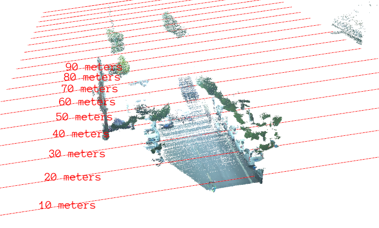
From the fitted ground plane and the camera plane, the angle of the camera relative to the ground can be determined. For a stereo or multi-camera setup, the depth values can be computed directly through triangulation; for a monocular camera, further processing is needed, using a neural network to obtain the depth values of the ground pixels.

method2:
If the vanishing-point coordinates in the image can be obtained, the projective properties of the vanishing point can be used to compute the angle of the camera relative to the ground, as shown in the figure:
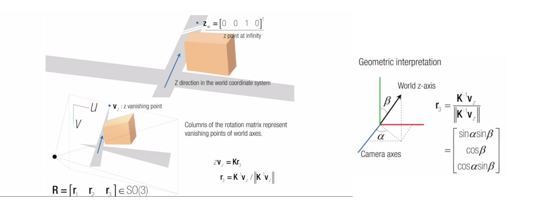
The position of the vanishing point in the world coordinate frame is [0, 0, 1, 0]. From its position in the image and the camera intrinsics, the third column of the rotation matrix can be obtained, and the angle can then be solved with some trigonometric functions. Here I recommend the video explanation at https://www.coursera.org/lecture/robotics-perception/vanishing-points-how-to-compute-camera-orientation-flqF4, as well as the algorithm introduction at https://github.com/thomasfermi/Algorithms-for-Automated-Driving
method3
The pitch angle of the camera relative to the ground is directly related to the position of the vanishing point. When the front of the vehicle rises, the row coordinate of the vanishing point moves toward the lower part of the image; conversely, when the rear of the vehicle rises and the front tilts down, the row coordinate of the vanishing point moves toward the upper part of the image. Using this relationship, we can derive the pitch-angle formula below: 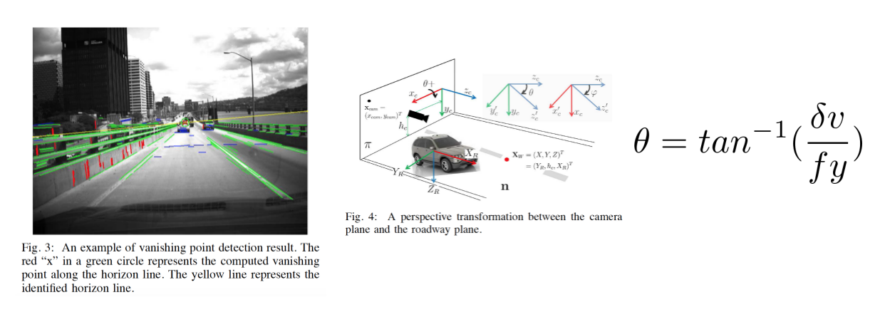
This method is also used in the pitch estimation in Apollo 5.0:
bool LaneBasedCalibrator::Process(const EgoLane &lane, const float &velocity,
                                  const float &yaw_rate,
                                  const float &time_diff) {
  float distance_traveled_in_meter = velocity * time_diff;
  float vehicle_yaw_changed = yaw_rate * time_diff;

  // Check for driving straight
  if (!IsTravelingStraight(vehicle_yaw_changed)) {
    AINFO << "Do not calibate if not moving straight: "
          << "yaw angle changed " << vehicle_yaw_changed;
    vp_buffer_.clear();
    return false;
  }

  VanishingPoint vp_cur;
  VanishingPoint vp_work;

  // Get the current estimation on vanishing point from lane
  if (!GetVanishingPoint(lane, &vp_cur)) {
    AINFO << "Lane is not valid for calibration.";
    return false;
  }
  vp_cur.distance_traveled = distance_traveled_in_meter;

  // Push vanishing point into buffer
  PushVanishingPoint(vp_cur);
  if (!PopVanishingPoint(&vp_work)) {
    AINFO << "Driving distance is not long enough";
    return false;
  }

  // Get current estimation on pitch
  pitch_cur_ = 0.0f;
  if (!GetPitchFromVanishingPoint(vp_work, &pitch_cur_)) {
    AINFO << "Failed to estimate pitch from vanishing point.";
    return false;
  }
  vanishing_row_ = vp_work.pixel_pos[1];

  // Get the filtered output using histogram
  if (!AddPitchToHistogram(pitch_cur_)) {
    AINFO << "Calculated pitch is out-of-range.";
    return false;
  }

  accumulated_straight_driving_in_meter_ += distance_traveled_in_meter;
  if (accumulated_straight_driving_in_meter_ >
          params_.min_distance_to_update_calibration_in_meter &&
      pitch_histogram_.Process()) {
    pitch_estimation_ = pitch_histogram_.get_val_estimation();
    const float cy = k_mat_[5];
    const float fy = k_mat_[4];
    vanishing_row_ = tanf(pitch_estimation_) * fy + cy;
    accumulated_straight_driving_in_meter_ = 0.0f;
    return true;
  }
  return false;
}
After driving straight for a certain distance, the pitch angle is computed using the vanishing point obtained from the intersection of the lane lines, while the pitch angle at the current moment is filtered with a histogram.
bool LaneBasedCalibrator::GetPitchFromVanishingPoint(const VanishingPoint &vp,
                                                     float *pitch) const {
  assert(pitch != nullptr);
  const float cx = k_mat_[2];
  const float cy = k_mat_[5];
  const float fx = k_mat_[0];
  const float fy = k_mat_[4];
  float yaw_check = static_cast<float>(atan2(vp.pixel_pos[0] - cx, fx));
  if (fabs(yaw_check) > params_.max_allowed_yaw_angle_in_radian) {
    return false;
  }
  *pitch = static_cast<float>(atan2(vp.pixel_pos[1] - cy, fy));
  return true;
}
The above code is located at https://github.com/ApolloAuto/apollo/blob/master/modules/perception/camera/lib/calibrator/laneline/lane_based_calibrator.cc
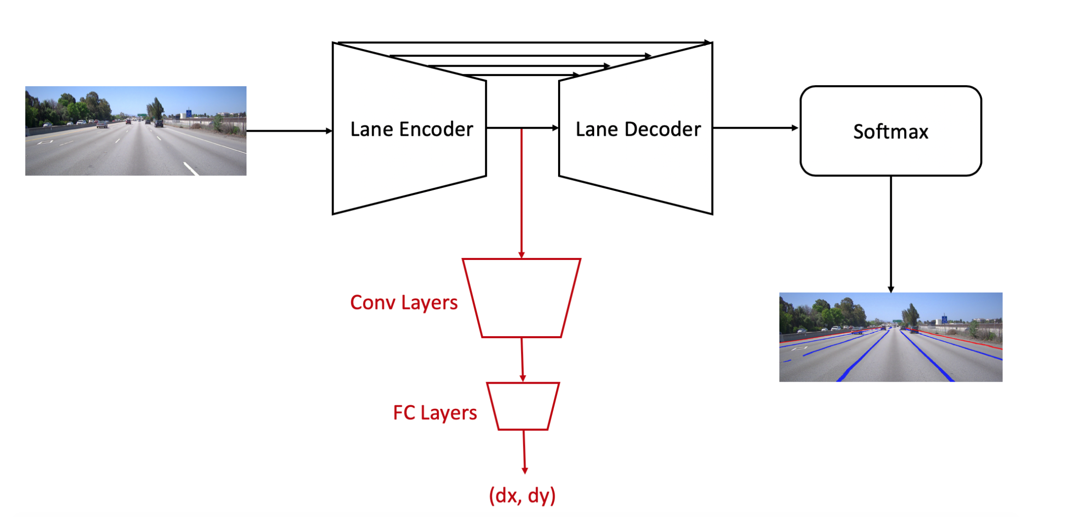
Regarding vanishing-point estimation, the code uses the intersection of two lane lines, and it also provides a vanishing-point estimation network. At the end of the encoder, convolutional layers and fully-connected layers are added to predict the offset positions dx and dy. The parameters of the vanishing-point network are trained separately, with the lane encoder’s parameters fixed.
method4
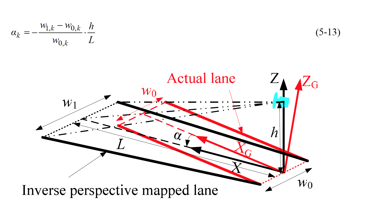
Because the vehicle’s pitch angle relative to the ground varies at each imaging instant, the parallelism of the lane boundaries in the BEV image (i.e., in the real environment) is disturbed. Using the condition that two widths should ideally be equal, the pitch angle can be approximately computed.

method5
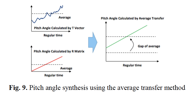
Because the vehicle drives on the road plane, the translation vector between two frames should theoretically be parallel to the road surface, and the pitch angle is taken to be the angle between the current camera coordinate frame and the translation vector, i.e., the angle between the translation vector and the camera’s optical axis. As shown in the figure below, from the translation vector we can obtain the absolute pitch angle at each moment, and from the rotation vector we can obtain the change in the pitch angle. The absolute pitch angle is obtained by averaging the pitch angles over a period of time, and is then propagated using the rotation matrix.

The open-source project openpilot also adopts a method that computes the pitch angle from camera odometry information:
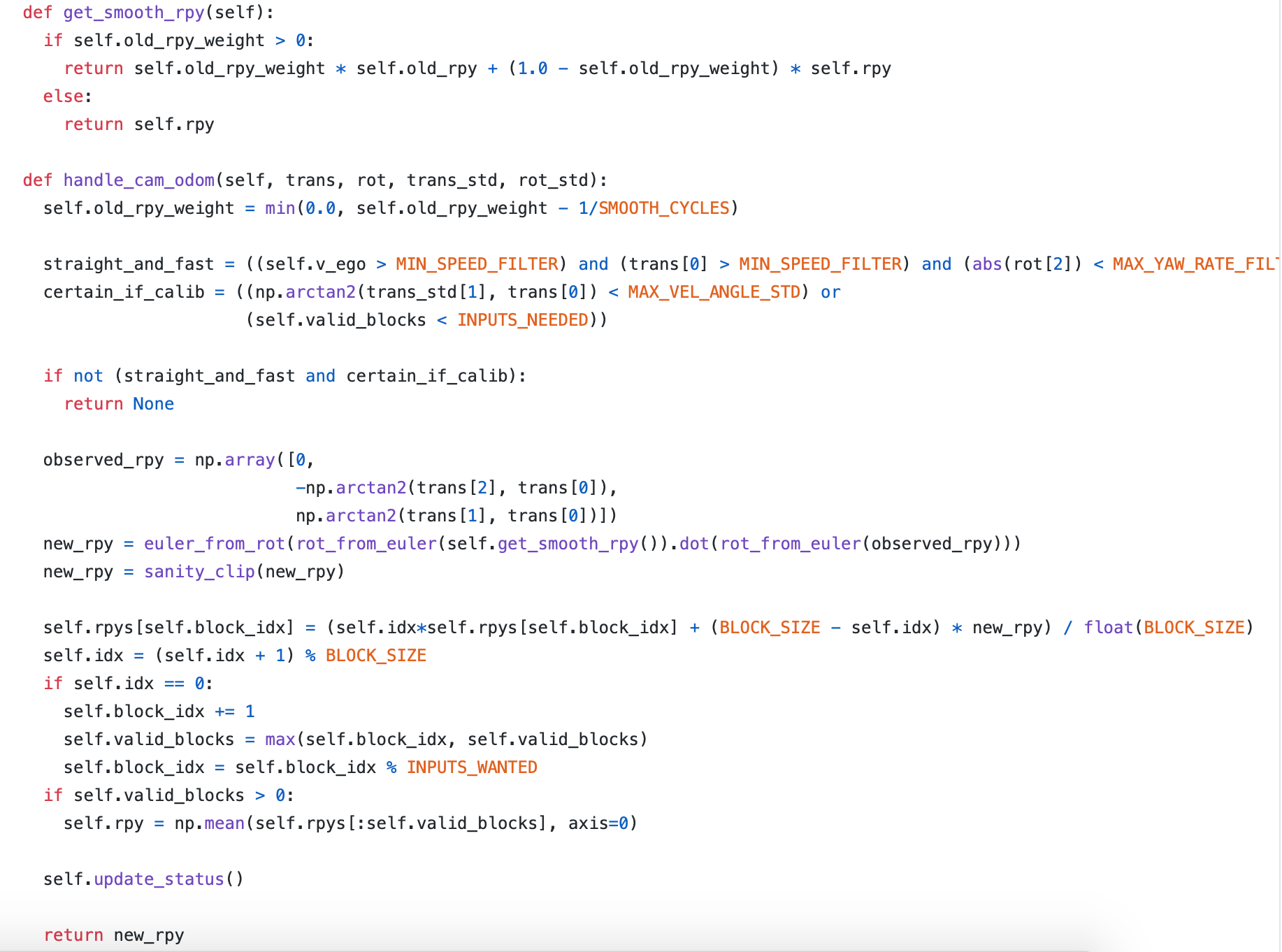
The computation is performed while driving straight, and it is weighted-smoothed with the historical rpy.
method6
If an IMU sensor is available, the trajectory computed by the IMU is aligned with the trajectory computed by visual odometry. Through hand-eye calibration, the extrinsics between the camera and the IMU can be obtained by solving for a transform that best aligns the trajectories estimated by the different sensors. The rotation matrix is solved via least squares, and decomposing it gives the pitch angle of the camera relative to the IMU. Since the IMU can estimate the gravity direction, the absolute pitch angle of the camera can also be determined.
method7
The bumpy motion of the vehicle on the ground causes the position and angle of the vehicle-mounted sensors relative to the ground to change, thereby affecting perception. We can estimate the pitch angle of the imaging device relative to the ground plane by computing the position of the vanishing line in the image, thereby reducing the impact of motion bumps on the perception results. Thus the problem of real-time calibration is transformed into the problem of estimating the vanishing-line position in real time. However, due to occlusion or incomplete lane lines, the vanishing line cannot be estimated in every frame. Therefore, what this patent does is to establish a mapping relationship between consecutive frames and, assuming the vanishing-point position of the previous frame is known, obtain the vanishing-point position of the next frame.
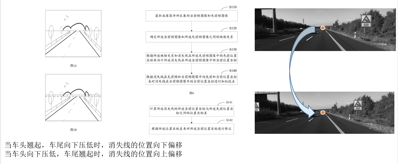
However, blindly setting the mapped vanishing-point position as the current frame’s vanishing-point position causes problems when the mapping relationship is wrong. It is observed that when the vehicle drives smoothly, the vanishing-line position is closer to the default position obtained from offline calibration, whereas during large bumps, the vanishing-line position is closer to the estimated position; the estimated position and the default position are therefore weighted-averaged.

Conclusion
Although there are many methods for pitch-angle estimation, they all have significant limitations — for example, requiring the vehicle to drive straight, or requiring that the camera’s ego-motion can be computed — so it remains an unsolved problem.
If you feel this article has had a positive impact on your understanding of your work, consider treating me to a cup of milk tea!

Comments