LiDAR Localization & Mapping
lidar slam study note
INTRODUCTION
Recently I read the “Building Autonomous Driving Localization from Scratch” column articles by Ren Qian on Zhihu, and learned a great deal; here I record some study notes on the content. Overall, Ren’s article series describes, from the ground up, the entire process of using LiDAR sensors for mapping and localization. The code is extensible and developed in a modular fashion, using the ROS system for message communication between different nodes. Each node has a workflow for its corresponding module, and within that workflow it invokes the core algorithm of the corresponding module. The modules include the data preprocessing node, the front-end LiDAR odometry node, the back-end graph-optimization node, the loop-closure detection node, and the visualization map-publishing node — essentially a form of multi-process parallel processing. Each part is described in detail below.
Data Preprocessing Module
int main(int argc, char *argv[]) {
    google::InitGoogleLogging(argv[0]);
    FLAGS_log_dir = WORK_SPACE_PATH + "/Log";
    FLAGS_alsologtostderr = 1;

    ros::init(argc, argv, "data_pretreat_node");
    ros::NodeHandle nh;

    std::string cloud_topic;
    nh.param<std::string>("cloud_topic", cloud_topic, "/synced_cloud");

    std::shared_ptr<DataPretreatFlow> data_pretreat_flow_ptr = std::make_shared<DataPretreatFlow>(nh, cloud_topic);

    ros::Rate rate(100);
    while (ros::ok()) {
        ros::spinOnce();

        data_pretreat_flow_ptr->Run();

        rate.sleep();
    }

    return 0;
}
As you can see, its main body continuously subscribes to the messages published by the rosbag and then hands them off to DataPretreatFlow for processing. The main job of the data preprocessing module is to subscribe to the following messages:
- /kitti/velo/pointcloud point cloud message
- /kitti/oxts/imu IMU message
- /kitti/oxts/gps/vel velocity message
- /kitti/oxts/gps/fix GNSS message
and to publish the following messages:
- /synced_cloud point cloud message after motion-distortion compensation
- /synced_gnss time-synchronized GNSS message (transformation)
The basic flow of the data preprocessing pipeline is as follows:
bool DataPretreatFlow::Run() {
    if (!ReadData())
        return false;

    if (!InitCalibration())
        return false;

    if (!InitGNSS())
        return false;

    while(HasData()) {
        if (!ValidData())
            continue;

        TransformData();
        PublishData();
    }

    return true;
}
- The subscribers parse the messages into data queues and time-synchronize all data other than the point cloud (IMU, velocity, GNSS).
- Obtain the extrinsic transformation matrix between the LiDAR and the IMU, so that the pose and velocity can be transformed into the LiDAR coordinate frame.
- Use GeographicLib to convert the GNSS coordinate frame into a local Cartesian coordinate frame with the first GNSS coordinate as the origin.
- When the synchronized data queues to be processed (cloud_data_buff, imu_data_buff, velocity_data_buff, gnss_data_buff) contain data, transform the data: transform the GNSS pose and velocity from the IMU coordinate frame to the LiDAR coordinate frame, and perform point cloud motion compensation based on a constant-velocity model.
- Publish the motion-distortion-corrected point cloud data and the GNSS pose (the pose of the LiDAR relative to the world).
The motion compensation function performs distortion compensation on the point cloud based on a constant-velocity model, i.e. it transforms the points of a single point cloud frame to the same instant in time — for example, transforming a scan frame spanning 0–100 ms to the 50 ms instant. The core compensation code is as follows:
    for (size_t point_index = 1; point_index < origin_cloud_ptr->points.size(); ++point_index) {
        float orientation = atan2(origin_cloud_ptr->points[point_index].y, origin_cloud_ptr->points[point_index].x);
        if (orientation < 0.0)
            orientation += 2.0 * M_PI;

        if (orientation < delete_space || 2.0 * M_PI - orientation < delete_space)
            continue;

        float real_time = fabs(orientation) / orientation_space * scan_period_ - scan_period_ / 2.0;

        Eigen::Vector3f origin_point(origin_cloud_ptr->points[point_index].x,
                                     origin_cloud_ptr->points[point_index].y,
                                     origin_cloud_ptr->points[point_index].z);

        Eigen::Matrix3f current_matrix = UpdateMatrix(real_time);
        Eigen::Vector3f rotated_point = current_matrix * origin_point;
        Eigen::Vector3f adjusted_point = rotated_point + velocity_ * real_time;
        CloudData::POINT point;
        point.x = adjusted_point(0);
        point.y = adjusted_point(1);
        point.z = adjusted_point(2);
        output_cloud_ptr->points.push_back(point);
    }
For each scan point, its scan angle is computed from its planar coordinates x, y; based on the scan angle, the compensation time is computed relative to the middle instant as origin; based on the time, velocity and angular velocity, the compensation rotation matrix and translation vector are computed; finally the coordinates are transformed by this rotation and translation to obtain the compensated point cloud, which is then used for the subsequent pose computation.
Front-End LiDAR Odometry Module
As the name suggests, its role is to take sequential point cloud data as input and output the LiDAR odometry pose. It subscribes to the “/synced_cloud” message and publishes the /laser_odom message. The idea behind the front-end odometry is fairly simple: match the current point cloud against a local map to solve for the pose. The matching method can be ICP, NDT or various variants, and of course other off-the-shelf LiDAR odometry methods such as LOAM and its variants can also be used. The local map is a keyframe window maintained by the front end and serves as the target point cloud during matching. The core code is as follows:
bool FrontEnd::Update(const CloudData& cloud_data, Eigen::Matrix4f& cloud_pose) {
    current_frame_.cloud_data.time = cloud_data.time;
    std::vector<int> indices;
    pcl::removeNaNFromPointCloud(*cloud_data.cloud_ptr, *current_frame_.cloud_data.cloud_ptr, indices);

    CloudData::CLOUD_PTR filtered_cloud_ptr(new CloudData::CLOUD());
    frame_filter_ptr_->Filter(current_frame_.cloud_data.cloud_ptr, filtered_cloud_ptr);

    static Eigen::Matrix4f step_pose = Eigen::Matrix4f::Identity();
    static Eigen::Matrix4f last_pose = init_pose_;
    static Eigen::Matrix4f predict_pose = init_pose_;
    static Eigen::Matrix4f last_key_frame_pose = init_pose_;

    // There are no keyframes in the local map container, which means this is the first frame of data
    // In this case, treat the current frame as the first keyframe and update the local map container and the global map container
    if (local_map_frames_.size() == 0) {
        current_frame_.pose = init_pose_;
        UpdateWithNewFrame(current_frame_);
        cloud_pose = current_frame_.pose;
        return true;
    }

    // Not the first frame, so perform normal matching
    CloudData::CLOUD_PTR result_cloud_ptr(new CloudData::CLOUD());
    registration_ptr_->ScanMatch(filtered_cloud_ptr, predict_pose, result_cloud_ptr, current_frame_.pose);
    cloud_pose = current_frame_.pose;

    // Update the relative motion between two adjacent frames
    step_pose = last_pose.inverse() * current_frame_.pose;
    predict_pose = current_frame_.pose * step_pose;
    last_pose = current_frame_.pose;

    // After matching, decide based on distance whether a new keyframe needs to be generated, and if so, update accordingly
    if (fabs(last_key_frame_pose(0,3) - current_frame_.pose(0,3)) +
        fabs(last_key_frame_pose(1,3) - current_frame_.pose(1,3)) +
        fabs(last_key_frame_pose(2,3) - current_frame_.pose(2,3)) > key_frame_distance_) {
        UpdateWithNewFrame(current_frame_);
        last_key_frame_pose = current_frame_.pose;
    }

    return true;
}
First, remove outliers from the current point cloud and filter it. If this is the first frame, set the current data as a keyframe (UpdateWithNewFrame). For other frames, perform scanMatch (e.g. ndt::align) to compute the pose of the current frame, then update the motion model to obtain the prediction for the next frame, while also deciding whether the frame is a keyframe based on the pose of the current frame and the pose of the previous keyframe. The generation of keyframes and the construction of the local map are as follows:
bool FrontEnd::UpdateWithNewFrame(const Frame& new_key_frame) {
    Frame key_frame = new_key_frame;
    // The purpose of this step is to save the keyframe's point cloud
    // Since a shared pointer is used, a direct copy only copies the pointer
    // In that case, no matter how many keyframes you put in the container, all of these keyframe point cloud pointers point to the same point cloud
    key_frame.cloud_data.cloud_ptr.reset(new CloudData::CLOUD(*new_key_frame.cloud_data.cloud_ptr));
    CloudData::CLOUD_PTR transformed_cloud_ptr(new CloudData::CLOUD());

    // Update the local map
    local_map_frames_.push_back(key_frame);
    while (local_map_frames_.size() > static_cast<size_t>(local_frame_num_)) {
        local_map_frames_.pop_front();
    }
    local_map_ptr_.reset(new CloudData::CLOUD());
    for (size_t i = 0; i < local_map_frames_.size(); ++i) {
        pcl::transformPointCloud(*local_map_frames_.at(i).cloud_data.cloud_ptr,
                                 *transformed_cloud_ptr,
                                 local_map_frames_.at(i).pose);

        *local_map_ptr_ += *transformed_cloud_ptr;
    }

    // Update the target point cloud for NDT matching
    // When there are still relatively few keyframes, do not filter, because there are not many points to begin with and making them too sparse would hurt the matching quality
    if (local_map_frames_.size() < 10) {
        registration_ptr_->SetInputTarget(local_map_ptr_);
    } else {
        CloudData::CLOUD_PTR filtered_local_map_ptr(new CloudData::CLOUD());
        local_map_filter_ptr_->Filter(local_map_ptr_, filtered_local_map_ptr);
        registration_ptr_->SetInputTarget(filtered_local_map_ptr);
    }

    return true;
}
Its main job is to maintain the local map and use it as the target point cloud for front-end matching. The figure below shows a result of NDT point cloud matching odometry: 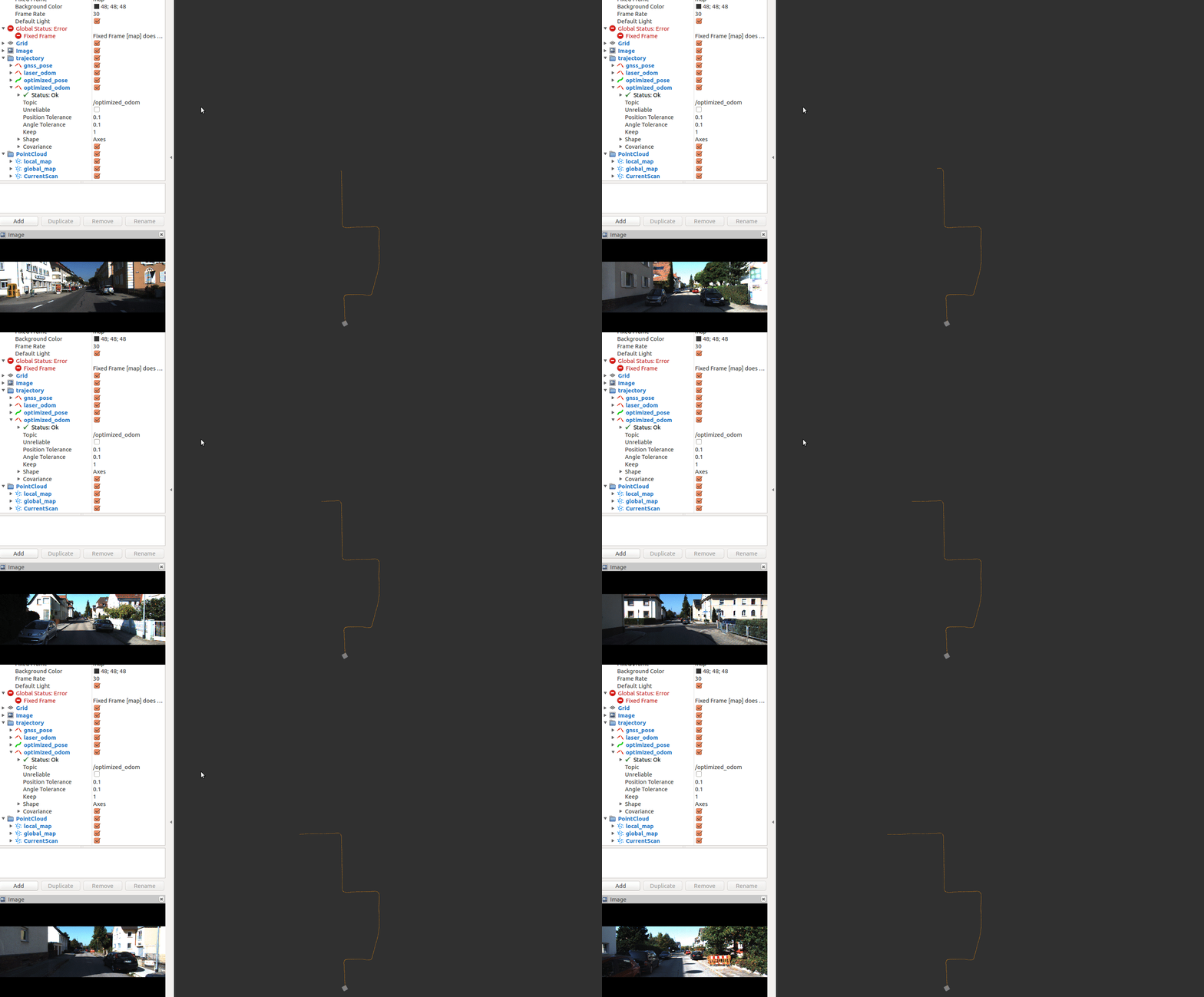
Back-End Mapping
The front-end LiDAR odometry provides relative constraints between frames. These constraints are sent to the back end and placed into the factor graph for optimization. Ren’s back end mainly includes three kinds of factors: an inter-frame odometry constraint, a GNSS prior constraint, and a detected loop-closure constraint. Overall, it is a typical pose-graph optimization problem. The input messages it receives are:
- /sync_cloud point cloud message (the back end saves keyframe point clouds to disk)
- /sync_gnss synchronized GNSS message
- /laser_odom LiDAR odometry message (the inter-frame constraint to be added to the factor graph)
- /loop_pose loop-closure message (current frame, loop frame, relative pose)
The output messages it publishes are:
- /transformed_odom pose in the GNSS coordinate frame
- /key_frame latest keyframe message (pose, index, time)
- /key_gnss latest GNSS message
- /optimized_key_frames sequence of keyframes after back-end optimization
The back-end process again reads the corresponding data messages, hands the current frame’s point cloud data, laser_odom data and gnss_pose data to the back end for processing, and finally publishes the processed results. Its core algorithm code is as follows:
bool BackEnd::Update(const CloudData& cloud_data, const PoseData& laser_odom, const PoseData& gnss_pose) {
    if (MaybeNewKeyFrame(cloud_data, laser_odom, gnss_pose)) {
        AddNodeAndEdge(gnss_pose);

        if (MaybeOptimized()) {
            SaveOptimizedPose(); // save backend optimized pose
        }
    }

    return true;
}
First, only keyframes are added to the optimization graph, with keyframes being identified based on distance. If the frame is a keyframe, then:
    if (has_new_key_frame_) {
        // Store the keyframe point cloud to disk
        std::string file_path = key_frames_path_ + "/key_frame_" + std::to_string(key_frames_deque_.size()) + ".pcd";
        pcl::io::savePCDFileBinary(file_path, *cloud_data.cloud_ptr);

        KeyFrame key_frame;
        key_frame.time = laser_odom.time;
        key_frame.index = (unsigned int)key_frames_deque_.size();
        key_frame.pose = laser_odom.pose;
        key_frames_deque_.push_back(key_frame);
        current_key_frame_ = key_frame;

        current_key_gnss_.time = gnss_odom.time;
        current_key_gnss_.index = key_frame.index;
        current_key_gnss_.pose = gnss_odom.pose;
    }
That is, the keyframe point cloud is stored to disk while the pose and other information are stored in the keyframe queue, and both current_key_frame_ and current_key_pose_ are set for the subsequent insertion of nodes and edges into the factor graph — adding, respectively, the keyframe node, the edge corresponding to the LiDAR odometry, the prior edge for the GNSS position, and the loop-closure edge. When the optimization conditions are met (a certain number of keyframes, a certain number of loops, and a certain number of GNSS measurements), optimization is performed:
bool G2oGraphOptimizer::Optimize() {
    static int optimize_cnt = 0;
    if(graph_ptr_->edges().size() < 1) {
        return false;
    }

    TicToc optimize_time;
    graph_ptr_->initializeOptimization();
    graph_ptr_->computeInitialGuess();
    graph_ptr_->computeActiveErrors();
    graph_ptr_->setVerbose(false);

    double chi2 = graph_ptr_->chi2();
    int iterations = graph_ptr_->optimize(max_iterations_num_);

    LOG(INFO) << std::endl << "------ Completed backend optimization #" << ++optimize_cnt << " -------" << std::endl
              << "vertices: " << graph_ptr_->vertices().size() << ", edges: " << graph_ptr_->edges().size() << std::endl
              << "iterations: " << iterations << "/" << max_iterations_num_ << std::endl
              << "time: " << optimize_time.toc() << std::endl
              << "error change before/after optimization: " << chi2 << "--->" << graph_ptr_->chi2()
              << std::endl << std::endl;

    return true;
}
When the optimization is complete, the optimized poses are assigned to the keyframes, yielding the optimized keyframes (all frames currently in the factor graph), which are then published to the other modules that need to subscribe to them.
Loop-Closure Detection Module
The loop-closure module comprises two steps, loop detection and matching. It sends the validated loop-closure relations to the back-end factor graph so that optimization can be performed when the conditions are met. The messages it subscribes to include the keyframe messages and key GNSS messages published by the back end:
- /key_frame keyframe message
- /key_gnss GNSS message corresponding to the keyframe Its computed output is:
- /loop_pose (index0, index1, relative_pose)
Loop-closure detection is responsible for finding the keyframe closest to the current keyframe. However, to avoid small loops, that keyframe must be a certain number of frames away from the current frame. Also, given the computational cost, once a loop is detected some frames need to be skipped before performing loop-closure detection again. After a keyframe is detected, registration needs to be performed, implemented as follows:
bool LoopClosing::CloudRegistration(int key_frame_index) {
    // Generate the map
    CloudData::CLOUD_PTR map_cloud_ptr(new CloudData::CLOUD());
    Eigen::Matrix4f map_pose = Eigen::Matrix4f::Identity();
    JointMap(key_frame_index, map_cloud_ptr, map_pose);

    // Generate the current scan
    CloudData::CLOUD_PTR scan_cloud_ptr(new CloudData::CLOUD());
    Eigen::Matrix4f scan_pose = Eigen::Matrix4f::Identity();
    JointScan(scan_cloud_ptr, scan_pose);

    // Match
    Eigen::Matrix4f result_pose = Eigen::Matrix4f::Identity();
    Registration(map_cloud_ptr, scan_cloud_ptr, scan_pose, result_pose);

    // Compute the relative pose
    current_loop_pose_.pose = map_pose.inverse() * result_pose;

    // Determine whether it is valid
    if (registration_ptr_->GetFitnessScore() > fitness_score_limit_)
        return false;

    static int loop_close_cnt = 0;
    loop_close_cnt ++;

    std::cout << "loop closure detected "<<  loop_close_cnt
              << ": frame" << current_loop_pose_.index0
              << "------>" << "frame" << current_loop_pose_.index1 << std::endl
              << "fitness score: " << registration_ptr_->GetFitnessScore()
              << std::endl << std::endl;
    return true;
}
First, a local map for matching is generated based on the detected keyframe index (keyframe_index - extend_frame_num, keyframe_index + extend_frame_num). The generated local point cloud map is a point cloud stitched together in the GNSS coordinate frame. The current scan is then used to generate a point cloud in the current coordinate frame, and the relative pose is computed through point cloud matching. The resulting loop (keyframe_index, current_index, relative_pose) is then sent to the back end to be added to the factor graph. Adding loop closures can effectively reduce ghosting error, because the objective function is precisely to minimize ghosting error, thereby effectively improving the consistency of the map. The figure below shows a loop-closure correction process:
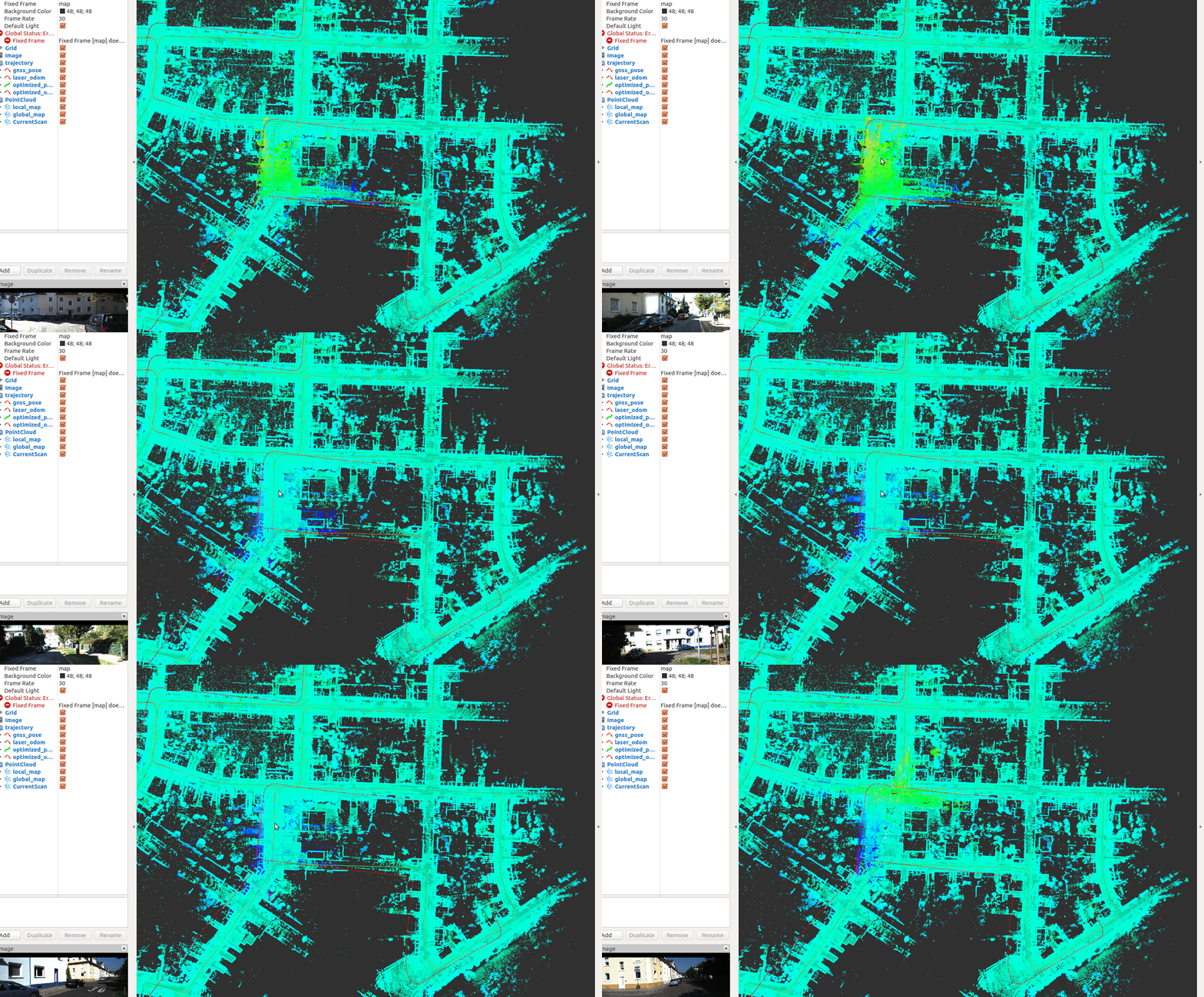 As you can see, after correction the loop-closure error has been effectively corrected.
Visualization Map-Publishing Module
After front-end and back-end processing, the current scan, local map and global map are generated. This information is processed and published to rviz for display; visualization makes it convenient to display and debug the results. The inputs it subscribes to are:
- /synced_cloud current-frame scan point cloud
- /key_frame keyframe processed by the back end
- /transformed_odom odometry in the GNSS coordinate frame
- /optimized_key_frames keyframes after back-end optimization The outputs it publishes are:
- /optimized_odom odometry after back-end optimization
- /current_scan
- /local_map
- /global_map
The pose-correction code here may have some issues and needs further analysis (todo).
While the program is running, you can call a ROS service such as save map at any time to save the map. The code it calls is:
bool Viewer::SaveMap() {
    if (optimized_key_frames_.size() == 0)
        return false;
    // Generate the map
    CloudData::CLOUD_PTR global_map_ptr(new CloudData::CLOUD());
    JointCloudMap(optimized_key_frames_, global_map_ptr);
    // Save the original map
    std::string map_file_path = map_path_ + "/map.pcd";
    pcl::io::savePCDFileBinary(map_file_path, *global_map_ptr);
    // Save the filtered map
    std::shared_ptr<VoxelFilter> map_filter_ptr = std::make_shared<VoxelFilter>(0.5, 0.5, 0.5);
    map_filter_ptr->Filter(global_map_ptr, global_map_ptr);
    std::string filtered_map_file_path = map_path_ + "/filtered_map.pcd";
    pcl::io::savePCDFileBinary(filtered_map_file_path, *global_map_ptr);
    return true;
}
The global map is generated and saved using the corrected poses and the point clouds stored on disk; the filtered map can also be saved for map-based localization.
Matching Module
The job of the Matching module is to perform LiDAR localization based on the point cloud map built earlier. In effect, it is a process of registering the current_scan against the local map, where the local map is cropped from the global map via BoxCrop. The Matching module performs localization only and does not require back-end optimization mapping; its global map is loaded directly. The inputs it subscribes to are:
- /synced_cloud current scan-frame point cloud
- /synced_gnss synchronized GNSS message
Its outputs are:
- /global_map loaded global map
- /local_map local map cropped based on the current-frame position
- /current_scan
- /laser_localization LiDAR localization information relative to the map (lidar relative to map)
The code for cropping the local map:
bool Matching::ResetLocalMap(float x, float y, float z) {
    std::vector<float> origin = {x, y, z};
    box_filter_ptr_->SetOrigin(origin);
    box_filter_ptr_->Filter(global_map_ptr_, local_map_ptr_);

    registration_ptr_->SetInputTarget(local_map_ptr_);

    has_new_local_map_ = true;

    std::vector<float> edge = box_filter_ptr_->GetEdge();
    LOG(INFO) << "new local map:" << edge.at(0) << ","
                                  << edge.at(1) << ","
                                  << edge.at(2) << ","
                                  << edge.at(3) << ","
                                  << edge.at(4) << ","
                                  << edge.at(5) << std::endl << std::endl;

    return true;
}
A cube is used to crop the local map, which serves as the target point cloud for matching.
Its method for updating the localization from the current-frame point cloud is as follows:
bool Matching::Update(const CloudData& cloud_data, Eigen::Matrix4f& cloud_pose) {
    // Remove outliers + cloud filter
    std::vector<int> indices;
    pcl::removeNaNFromPointCloud(*cloud_data.cloud_ptr, *cloud_data.cloud_ptr, indices);

    CloudData::CLOUD_PTR filtered_cloud_ptr(new CloudData::CLOUD());
    frame_filter_ptr_->Filter(cloud_data.cloud_ptr, filtered_cloud_ptr);

    static Eigen::Matrix4f step_pose = Eigen::Matrix4f::Identity();
    static Eigen::Matrix4f last_pose = init_pose_;
    static Eigen::Matrix4f predict_pose = init_pose_;

    if (!has_inited_) {
        predict_pose = current_gnss_pose_;
    }

    // Match against the map
    CloudData::CLOUD_PTR result_cloud_ptr(new CloudData::CLOUD());
    registration_ptr_->ScanMatch(filtered_cloud_ptr, predict_pose, result_cloud_ptr, cloud_pose);
    // Transform the current-frame point cloud into the global coordinate frame based on the pose and publish it
    pcl::transformPointCloud(*cloud_data.cloud_ptr, *current_scan_ptr_, cloud_pose);

    // Update the relative motion between two adjacent frames
    step_pose = last_pose.inverse() * cloud_pose;
    predict_pose = cloud_pose * step_pose;
    last_pose = cloud_pose;

    // After matching, decide whether the local map needs to be updated
    std::vector<float> edge = box_filter_ptr_->GetEdge();
    for (int i = 0; i < 3; i++) {
        if (fabs(cloud_pose(i, 3) - edge.at(2 * i)) > 50.0 &&
            fabs(cloud_pose(i, 3) - edge.at(2 * i + 1)) > 50.0)
            continue;
        ResetLocalMap(cloud_pose(0,3), cloud_pose(1,3), cloud_pose(2,3));
        break;
    }

    return true;
}
It makes fairly heavy use of the static feature.
A schematic of LiDAR-map-based LiDAR localization is shown below: 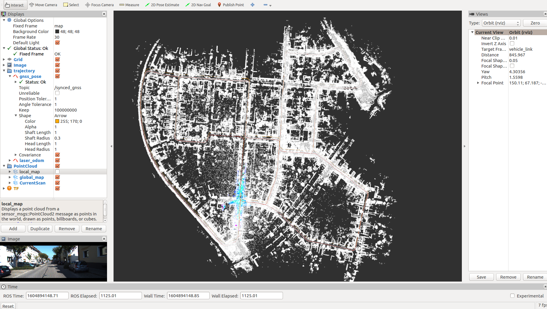
Finally, thanks to Ren (https://www.zhihu.com/people/ren-gan-16) for his work!!!
Comments